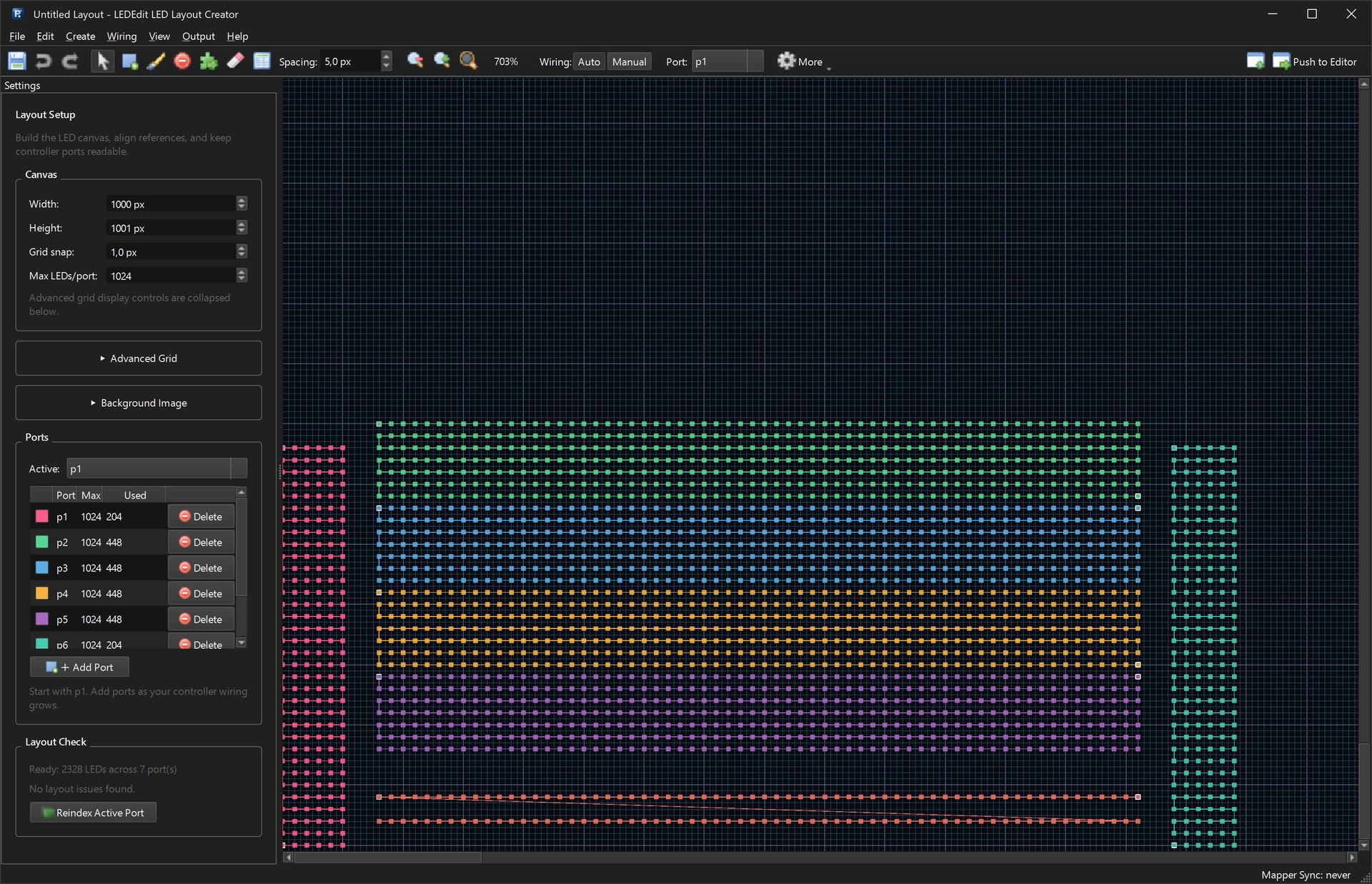
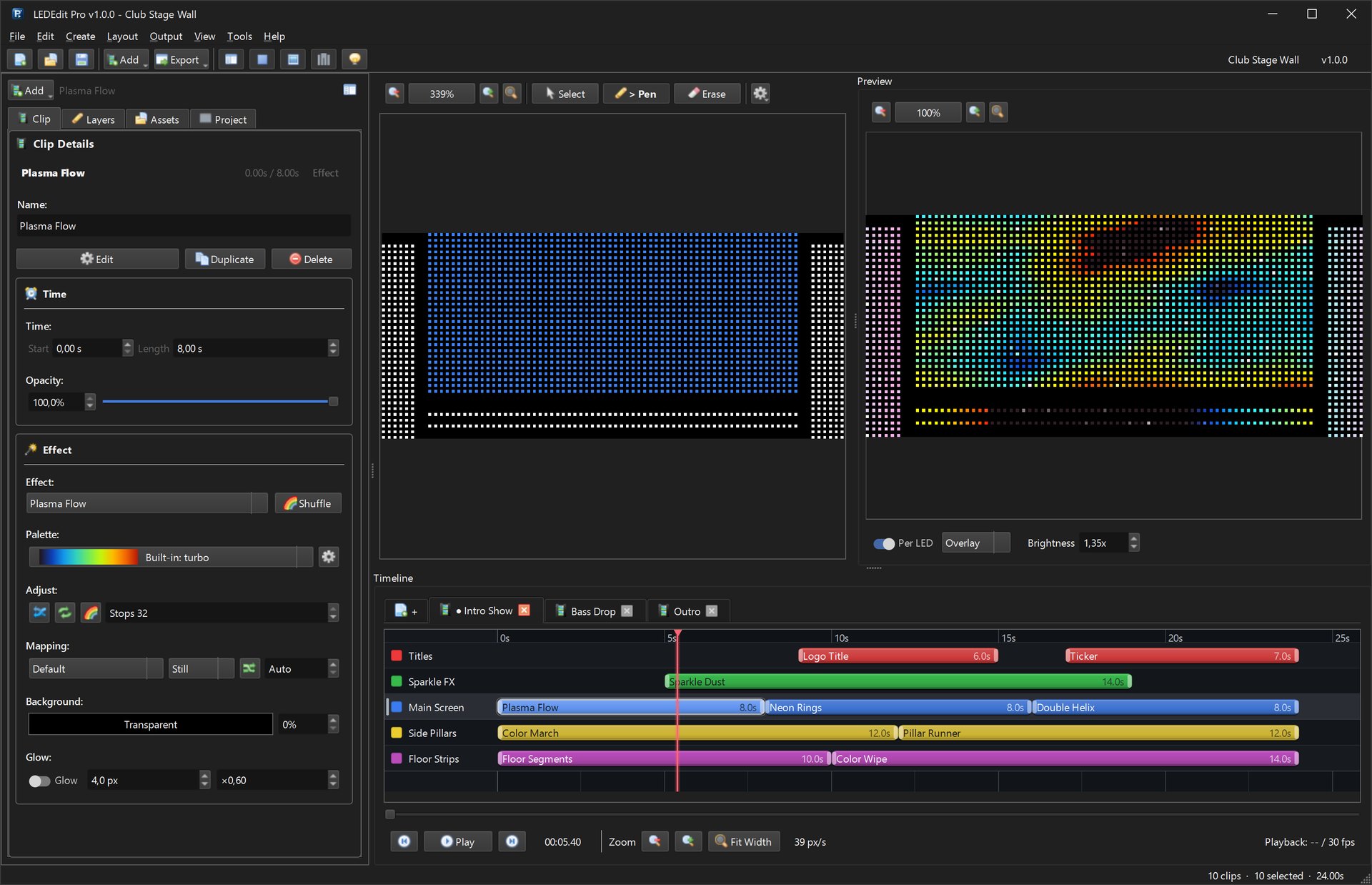
The layout is the map LEDEdit uses to translate video frames into pixel data — get it wrong and text comes out mirrored, sections play in the wrong order, or half the wall stays dark. There are three ways to build one: draw manually, generate automatically, or import a BMP plan from Photoshop. This guide covers all three plus the port wiring that connects map to hardware.
Recommended for new shows: LEDEdit Pro 2026
Manual layout mapping is the slow way. LEDEdit Pro 2026 ships an LED Layout Creator with millimetre grid, serpentine/linear/manual wiring, per-port limit checks and DXF import/export — plus live per-LED preview before anything hits the SD card.
See LEDEdit Pro 2026 features Buy once — €99 lifetimeBefore you draw: the wiring plan
Sketch on paper first: wall dimensions, pixel pitch, where each strip starts and ends, which controller port feeds which section, and the data direction (left-to-right? bottom-to-top? snaked?). Every layout method below encodes this plan — 10 minutes with a pencil saves 2 hours of re-mapping.
Golden rule: the layout must follow the physical data path, pixel by pixel. Software order = wire order. Any deviation mirrors or scrambles the image.
Method 1: manual layout
Best for signs, outlines and small matrices under ~1,000 pixels.
- New project → set matrix size to your total bounding box (e.g. 128×32 for a text sign).
- Manual layout window: click-drag to paint pixels where strips physically run. Zoom to fit, enable the ruler, work section by section.
- Set the port: assign the painted block to the controller port it hangs on.
- Verify direction: play a left-to-right chase in preview — if it runs right-to-left on hardware, flip the section direction (don’t rewire).
Manual painting is precise but slow past a few thousand pixels — that’s what the auto tools are for.
Method 2: auto layout (AutoLX / AutoAX)
Best for rectangular matrices and regular grids.
- AutoLX fills a rectangle with serpentine (snake) wiring automatically: set width, height, start corner and snake axis, and it generates the full pixel order plus port assignment in one click.
- AutoAX handles linear (non-snake) runs — all rows flowing the same direction — for walls wired with straight feeds.
- After generation, use the quick-remove connection tool to delete stray pixels outside your shape (e.g. corners cut for frames), and the line tool to patch gaps.
Always run the layout check after auto-generation: it flags unconnected pixels, double assignments and port overflows before you export.
Method 3: Photoshop BMP import
Best for irregular shapes — logos, letters, architectural outlines.
- New Photoshop file sized to your pixel grid (1 px = 1 LED), background black.
- Draw the shape with the rectangle/line tools in white (or per-section colors matching your wiring plan).
- Save As BMP, 24-bit, no compression — LEDEdit’s importer chokes on RLE compression and 32-bit alpha.
- Import in LEDEdit: layout → import BMP → the software converts lit pixels to a pixel map.
- Assign ports and direction per section exactly as wired, then connect sections in series in the wiring view.
Resolution trap: a 1920×1080 BMP for a 128×32 wall imports as garbage. Size the BMP to the LED grid, not the video grid.
Connecting ports to the layout
The port tool binds map sections to hardware outputs:
- Select a section → Port tool → click the controller port number.
- Connect in series for multi-section runs on one port — order matters; section 2’s input is section 1’s output.
- Failed connection? The red marker means direction mismatch or a gap: flip section direction or paint the missing bridge pixel.
- Re-run preview chase per port to confirm order before export.
Frame-shaped and irregular layouts
For frames, arches and rings: draw the outline as a 1-pixel path (line tool or BMP), then use manual connection along the path direction. Keep a consistent clockwise or counter-clockwise order — mixing directions in one port splits text and effects at the seam.
Troubleshooting
| Symptom | Fix |
|---|---|
| Image mirrored | Section direction flipped — reverse it in layout, don’t rewire |
| Sections play in wrong order | Series connection order wrong — reorder in wiring view |
| Dark gaps | Unconnected pixels — run layout check, paint bridges |
| Port overflow error | Too many pixels on one port — split across ports |
| BMP imports blank | Wrong BMP format — 24-bit uncompressed, 1px = 1 LED |
Related guides
- LED text layout — letters and tickers on your new map
- T-1000S tutorial — from map to hardware
- Power supply guide — feed what you mapped
- Free downloads — LEDEdit installers
- LEDEdit Pro 2026 features — Layout Creator with DXF