Already have a layout drawn in LEDEdit or a CAD program? You do not have to place every pixel again. LEDEdit Pro 2026 reads LEDEdit-style DXF files — LEDs, wires and all — and turns them into ports you can check and fix.
Two ways to import
| Where | Menu | Best for |
|---|---|---|
| Main window | Layout → Import DXF Layout… | A DXF that is already correct: it becomes the project’s LED layout straight away |
| LED Layout Creator | File → Import DXF… | Checking and fixing ports, numbering and limits before you use the layout |
If the LED Layout Creator already contains LEDs, it asks whether to replace the layout (Yes) or merge the DXF into it (No). Merged LEDs go onto the ports after your existing ones.
What LEDEdit Pro reads from the DXF
- Circles are LEDs. Circles on a layer named
LEDSor drawn in cyan are used. If there are none, every circle counts. - Lines are wires. Lines on a layer named
WIRESor drawn in green are used. If there are none, the other lines count. - A wire must start and end on an LED, within about three LED radii of its centre.
- Each connected chain becomes one port. The numbering follows the wire, starting at the chain end furthest to the left.
- DXF files that use a comma as decimal separator (European locale) are handled automatically.
Check the result
After File → Import DXF… the status bar shows Imported DXF: N LEDs, C connections. Two quick checks:
- N should be your real pixel count.
- For fully wired runs, C = N − number of ports — every LED is connected to the next one, except the last LED of each run.

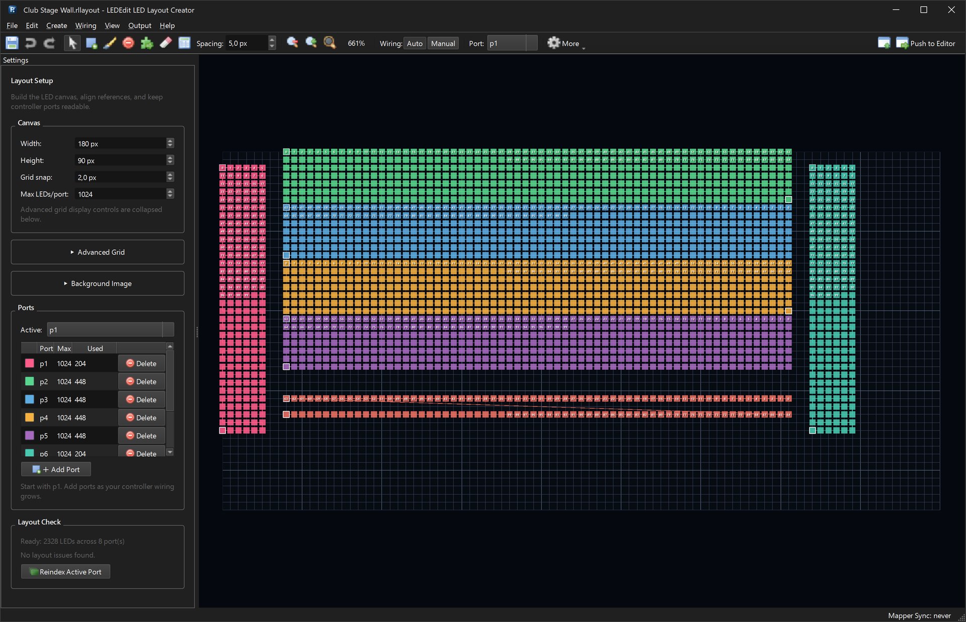
In the example above: 2,328 LEDs, 2,321 connections and 7 ports, because 2,328 − 7 = 2,321. Everything is wired.
LEDEdit DXF files use small coordinates, so the imported LEDs can look tiny in a corner of the canvas. Zoom in (View → Zoom In) to work on them.
Fix common import problems
Many ports with only one LED each — the wires did not reach the LEDs, so every LED became its own port.
- Wiring → Auto Number / Ports…: choose an order (Rows zigzag, Columns top down, Nearest path, …) and LEDs per port. The preview line shows how many ports you will get and the first and last LED before you click OK.
- Or draw the missing wires with Connect LEDs (C) in Manual wiring mode.
Port numbers do not match your cables — right-click a port → Move LEDs To… to move a run to the right output.
Numbering starts at the wrong end — renumber that area with Auto Number / Ports…, or rewire it with the Connect tool.
Port limit too low — imported ports start with a Max of 1,024 LEDs. Set the Max column to your controller’s limit, for example 2,048 per output on a T-1000. See port limits and wiring gaps.
When Layout Check says Ready: … LEDs across … port(s), click Push to Editor.
Going the other way
Layout → Export DXF Layout… in the main window (or Output → Export DXF in the LED Layout Creator) writes a DXF in LEDEdit’s own style. Everything goes on layer 0, with green wires and port labels. Use it for the DXF + AVI fallback with the free LEDEdit.