Every LED show starts with the layout: where each pixel sits and in which order the data travels through it. If the layout is wrong, even the best effect lands on the wrong LEDs. LEDEdit Pro 2026 includes the LED Layout Creator for exactly this job — and it reads and writes LEDEdit DXF files, so existing layouts keep working.
Two ways to get a layout into your project
In the main window, open the Layout menu:
- Import DXF Layout… — load an existing LEDEdit/DXF layout with its LEDs and wiring.
- Open LED Layout Creator… — draw or edit the layout in its own window.
You can also start with an imported DXF and fine-tune it in the creator.
1. Set up the canvas
The Layout Setup panel on the left holds the basics:
- Width / Height — the size of the canvas.
- Grid snap — the step LEDs snap to when you place or move them.
- Max LEDs/port — the default capacity for new ports. Set this to your controller’s per-output limit.
- Advanced Grid — grid display, opacity and a stronger line every N cells.
- Background Image — load a photo or plan of the installation and adjust its opacity to trace over it.
Tip: Tracing a straight-on photo of a sign or facade is the fastest way to get LED positions right for irregular shapes.
2. Plan your ports
A port is one data output of your controller. The Ports table shows every port with its Max and Used LED count, so you see immediately when a run is too long.
- The layout starts with p1; click Add Port as your wiring grows (up to 64 ports).
- The Active port decides where new LEDs go.
- Right-click a port to set it active, move its LEDs to another port, reindex it or delete it.
Match ports to your hardware: an 8-output K-8000 / T-8000 or T8K-U-1024 needs up to 8 ports, a T1K-U-2048 has one output with up to 2,048 LEDs. The controller list shows outputs per family.
3. Place LEDs
The Create menu holds the tools (shortcut in brackets):
| Tool | What it does |
|---|---|
| Select / Move (V) | Select, drag and move LEDs |
| Add LED (A) | Click to place one LED |
| Draw LEDs (P) | Hold the mouse and drag to paint LEDs |
| Delete LED (Del) | Click an LED to delete it |
| Connect LEDs (C) | Draw a wire between two LEDs on the same port |
| Erase Connection (E) | Remove an existing wire |
For matrices, strips and panels use Create → Pattern Builder…. It builds a numbered LED matrix and previews the wire route before you stamp it on the canvas:
- Rows and Columns, Spacing X / Y
- Wire Route — Rows Linear, Rows Serpentine, Columns Linear or Columns Serpentine
- Start Corner — top left, top right, bottom left or bottom right
- Reverse numbering — flip the LED order after the route is calculated
- Insert Mode — Add to current port, Create with new port or Just LEDs (no connections)
Click Use Pattern, then click the canvas where LED 1 should land.
Serpentine or linear? Most LED matrices and curtain panels are wired serpentine (zig-zag): row 1 left to right, row 2 right to left. Strips that each start on the same side are linear. Always check which corner the data enters — that’s your start corner.
4. Wire and number the layout
The Wiring menu controls how LEDs get connected:
- Auto — new LEDs are automatically wired to the previous LED on the same port.
- Manual — you draw every connection yourself with Connect LEDs (C).
- Fix Wiring Gaps… — repairs breaks in a port’s chain.
- Auto Number / Ports… — numbers the whole layout and assigns ports in one step.
Select a group of LEDs and use Create → Connect All Selected to wire them in index order per port.
5. Run Layout Check
The Layout Check box sums up the layout — for example “Ready: 2328 LEDs across 8 port(s)” and “No layout issues found”. If it reports problems, fix them before you animate: a missing connection or an over-full port turns into wrong pixels on the controller. Reindex Active Port renumbers the active port’s LEDs in wiring order.
6. Export the layout or push it into the editor
The creator’s Output menu:
- Export DXF — a LEDEdit-compatible DXF with LEDs and wiring.
- Export PNG — an image of the layout for documentation.
- Export Reference BMP… — a clean LEDEdit-style bitmap reference.
- Export CSV — LED positions and order as a spreadsheet.
- Push to LED Mapper (the Push to Editor button) — saves the layout and sends it to the main project.
- Pull from LED Mapper — loads the project’s current layout back into the creator.
Back in the editor, the Project tab lists the LED count per port so you can confirm the push.

7. Decide which LEDs each layer drives
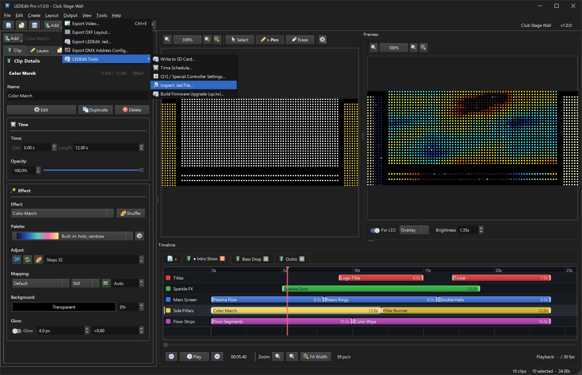
With the layout in place, layers decide where content plays. Select a layer and paint its mask over the LEDs with the Pen tool — the main screen on one layer, the pillars on another.

Common layout mistakes
- Wrong start corner — the animation looks mirrored or runs backwards. Rebuild the pattern with the correct start corner or use Reverse numbering.
- Port over capacity — an output can only drive as many LEDs as the controller allows. Watch the Used column and split long runs across ports.
- Mixing linear and serpentine — every second row looks shifted. Match the wire route to the real cabling.
- Scaling the video later — keep the project canvas; if you hand DXF + AVI to free LEDEdit, don’t resize the video (why).