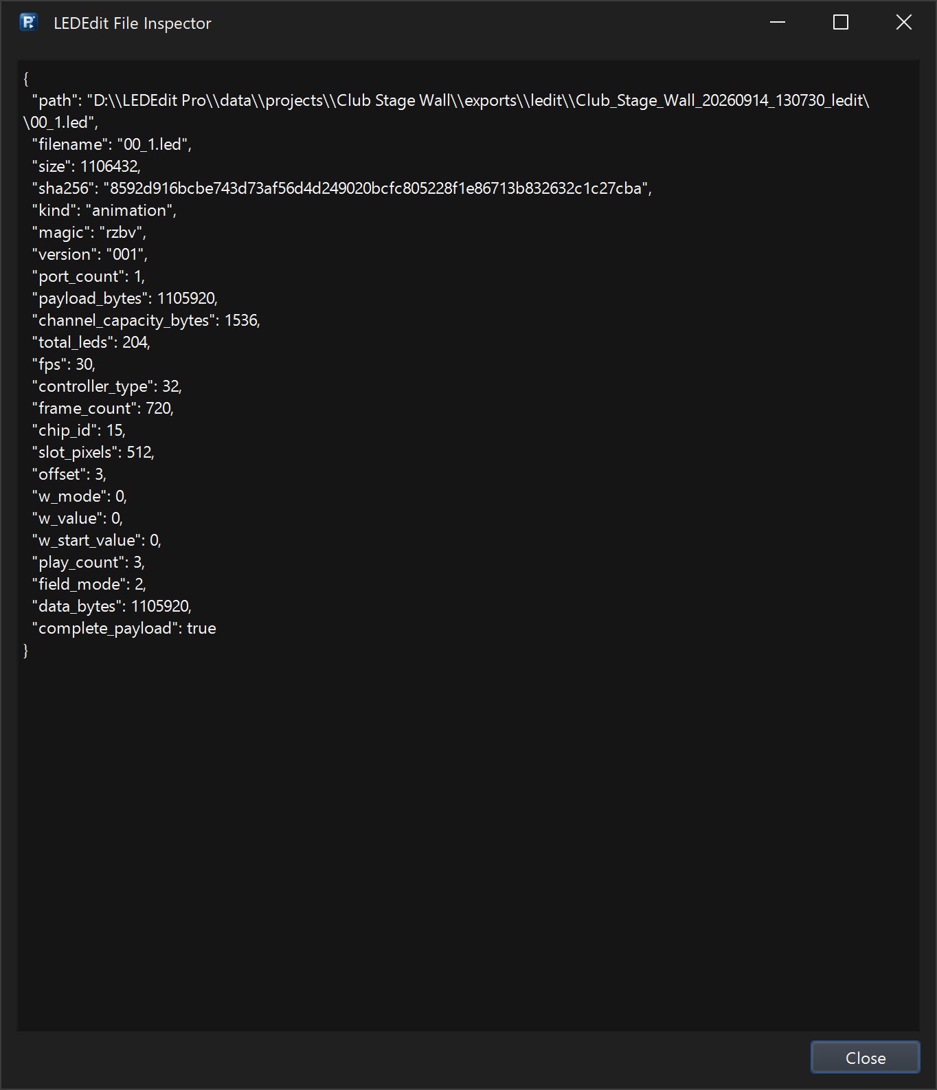
The T-1000S is the single-output SD-card controller found in almost every small pixel install — shop signs, outlines and small matrices. It has one data port, three front-panel buttons and a single SD slot, but 90% of “T-1000S not playing” issues come from wiring the wrong way or picking the wrong LEDEdit profile. This tutorial covers pinout, button logic, four wiring methods and the exact LEDEdit export.
Recommended for new shows: LEDEdit Pro 2026
The download above is the old free community release (good for existing setups). For new projects use LEDEdit Pro 2026 — multi-layer timeline, 151 effects, LED Layout Creator with DXF import/export, live per-LED preview and direct .led export for 19 controller families.
T-1000S at a glance
- One SPI output, up to 2,048 LEDs (some firmware caps at 1,024 — see label)
- SD card: 2–32 GB, FAT32 only,
.ledfiles in root - Power: 5–24V DC in (powers logic, not pixels — pixels need their own supply)
- Buttons: MODE, SET, SPEED on the front; 1602 or 0.96" OLED shows file and speed
- Chips: WS2811, WS2812B, UCS1903, SM16703, TM1809 etc — depends on firmware; label often says “T-1000S-WS2811”
Label matters: “T-1000S” and “T-1000” are different families. A T-1000S file will not play on a plain T-1000 and vice versa. Read the white sticker on the metal case.
Pinout and ports
Front view (left to right):
| Marking | Pin | What it is |
|---|---|---|
| V+ / +5V | Power in + | Controller logic 5V (or 7.5–24V on wide-range boards) |
| GND / - | Ground | Logic ground — must tie to pixel ground |
| DAT / D | Data out | SPI data to first pixel DI |
| CLK / C | Clock | Only for 4-wire chips (APA102, P9813); leave unconnected for WS2811 |
| SD slot | Card | Push-to-click micro or full SD depending on batch |
Rear or side screw terminals mirror the same labels plus sometimes OUT+ / OUT- for the data cable shield.
Power wiring: controller V+ and GND come from a small 5V 1A supply or share the pixel supply via a DC-DC buck. Never power pixels through the controller — run a thick separate feed to the strip.
Ground is mandatory: If controller and strip do not share GND, the data line floats and pixels flicker or stay dark. Always connect controller GND to the strip GND at the first pixel.
Button functions
| Button | Short press | Hold 2 sec | Hold 5 sec |
|---|---|---|---|
| MODE | Next .led file (cycles 00_01 → 00_02 → ...) | Enters brightness menu | Enters speed/dimming submenu on some firmware |
| SET | Confirm / play selected file | Enters settings (chip type on older units) | Reset to file 1 |
| SPEED + / SPEED - | +1 or -1 speed step (1–16) | Fast scroll | – |
Startup behavior without button presses: on power-on the controller loads the last file it played (or the lowest-numbered file) and starts at speed 8 (mid). Display shows:
T-1000S       PLAY
File: 00_01.led   Spd:08
LEDs: 0640  Chip:WS2811
If you see No File or No SD, the card is exFAT, empty or file-named wrong (see SD section).
4 wiring methods – pick one that matches your pixels
All methods share a rule: data direction matters. The arrow printed on the strip points away from the controller. DI (Data In) faces the controller, DO (Data Out) faces the next strip.
Method 1: Single strip – direct (most common)
- Controller DAT → Strip DI
- Controller GND → Strip GND
- Strip V+ → Power supply V+ (5V or 12V per strip spec)
- Strip GND → Power supply GND → Controller GND (star ground)
Use for shop outline strips, single runs under 5 m.
Method 2: Long run – power injection every 5 m
For 10–20 m WS2811 strings:
- Data chain continues DI → DO along the whole run (one continuous data line from T-1000S)
- Power injected at each 5 m segment from the supply: tap V+ and GND to the copper pads mid-strip
- Keep GND continuous between all injection points and the controller
Diagram described: T-1000S DAT line running through three 5 m WS2811 segments; V+ and GND from a 5V 60A supply branching to each segment’s pads; common GND line back to controller.
Method 3: Matrix – serpentine rows
For a 64×16 sign (1,024 LEDs) or 32×32 panel:
- Lay pixels in serpentine so data snakes row to row — LEDEdit Mark called “Serpentine Rows” must match physical snake
- Controller DAT enters top-left pixel; after each row the strip folds back
- In LEDEdit, create the layout as Pattern Builder → 64 columns × 16 rows → Serpentine
Mismatch here causes the second row to appear mirrored. Toggle serpentine in layout, not in wiring, to fix.
Method 4: 4-wire pixels – use CLK (APA102, P9813, LPD8806)
- Controller DAT → Strip DI
- Controller CLK → Strip CI (Clock In)
- GND and V+ as before
For WS2811 leave CLK unconnected — do not tie to GND or V+.
Controller selection in LEDEdit – T-1000S-WS2811
- File → LED Type → choose family
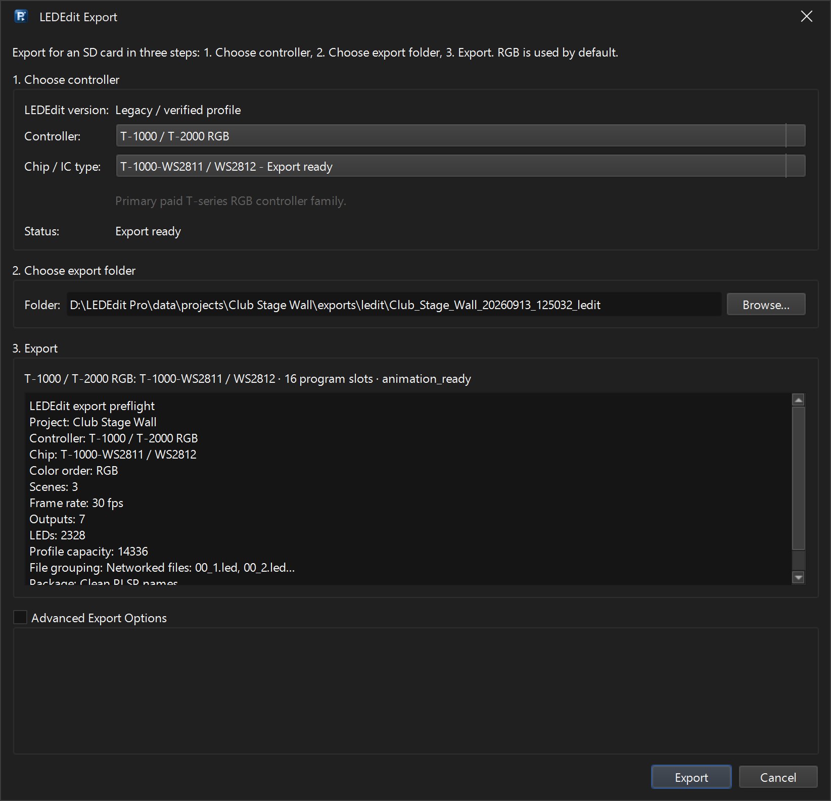
T-1000S, chipWS2811(or exact:T-1000S-WS2811,T-1000-WS2811-800kHzon 2014). In Pro: Output → Export LEDEdit .led → Controller: T-1000 / T-2000 RGB → Chip: T-1000-WS2811. - Set Pixel count to your total — e.g. 640 for a shop sign outline, 1024 for a 64×16 matrix. Leave a 10% headroom under 2,048.
- Color order: WS2811 strips are usually
GRBon 12V andRGBon 5V — check datasheet. If red and green are swapped, that is the only setting to change. - Clock speed: 800 kHz for WS2811; 400 kHz for older TM1809. Wrong speed gives stutter.
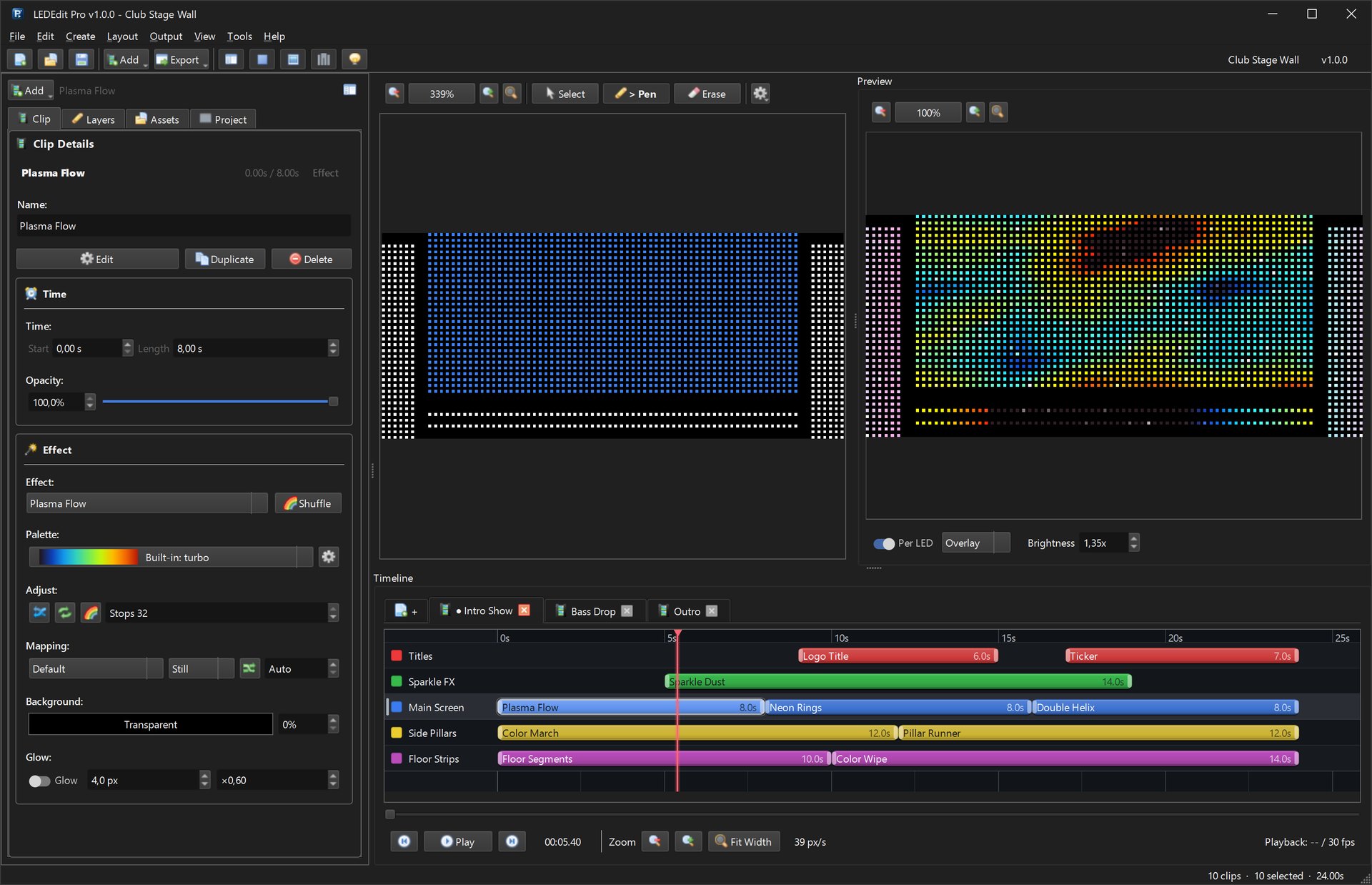
Build the layout, push to editor, add effects, preview per-LED, then export:
- Filename
00_01.ledfor auto-play; place one file only to start - FPS 30; brightness 80% to save power and heat
- In Pro, watch the preflight line:
T-1000/2000 RGB | WS2811 | 640 LEDs | 1 scene | 30 fps — OK
SD card: format, files and first boot
Format 2–32 GB card as FAT32, 4096 bytes, Quick Format. Copy to root, not a folder:
E:\ (FAT32)
├── 00_01.led      ← show file (auto-play)
├── 00_02.led      ← optional second file (next press of MODE)
└── (no folders)
File naming rules: T-1000S respects
00_01.ledthrough00_16.led(16 files max) and sometimes01.ledlegacy names. Use zero-padded names. AvoidMyShow.led— some firmwares ignore it.
Boot:
- Power off controller
- Insert SD until click; ensure lock switch on adapter is unlocked
- Power on — screen shows file name, then
PLAY; pixels light within 2 seconds - Press MODE to cycle files; press SPEED to adjust speed; hold SET to confirm file lock
Troubleshooting
| Symptom | Cause | Fix |
|---|---|---|
No SD / No File | exFAT, locked switch or wrong name | Reformat FAT32, unlock, rename to 00_01.led |
| Dark after boot, display says PLAY | Data/GND not sharing ground | Connect controller GND to pixel supply GND |
| Random flicker | Missing power injection or CLK tied wrong | Inject power every 5 m, leave CLK floating for WS2811 |
| Wrong colors (R↔G) | Color order | Re-export with GRB vs RGB swap |
| Only first half lights | Pixel count set low or strip cut wrong | Check count in LED Type equals physical LEDs; verify DI/DO direction |
| Speed always max | Stuck button | Check buttons not pressed by case; hold MODE 5 sec to reset |
For deeper export debugging see the LEDEdit fallback guide and the T-1000S controller page for chip lists.