
The T-600K is the six-port workhorse of the K-series family — the controller you meet in medium building facades, stage backdrops and long shopping-mall runs. It speaks LEDEdit-K, runs online over Ethernet or offline from SD, and drives thousands of pixels across its ports. This tutorial covers pinout, single and multi-controller wiring, software setup and the SD export that makes it standalone.
Recommended for new shows: LEDEdit Pro 2026
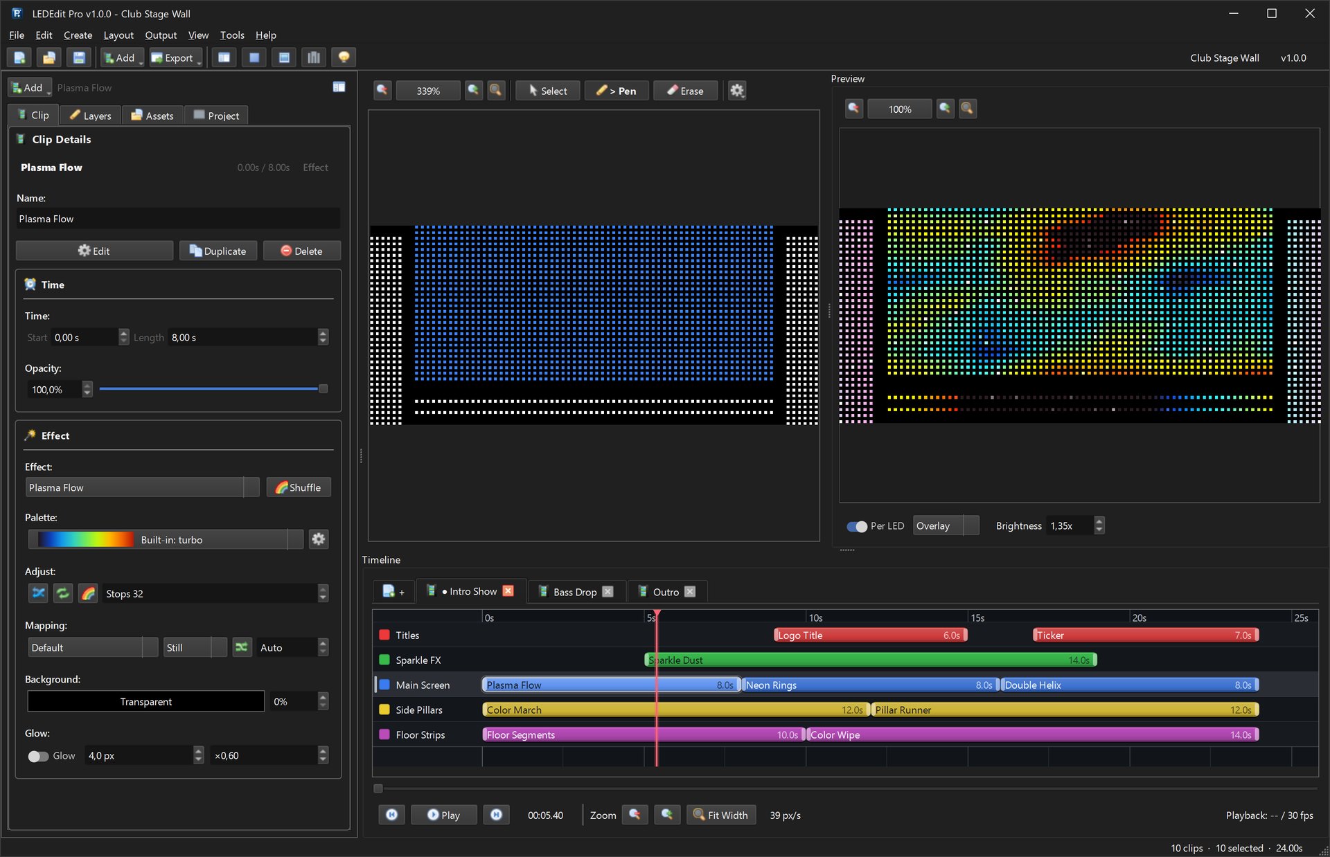
This guide covers the free LEDEdit-K community release. For new projects use LEDEdit Pro 2026 — multi-layer timeline, 151 effects, LED Layout Creator with DXF import/export, live per-LED preview and direct .led export for 19 controller families including T-600K.
T-600K at a glance
- 6 SPI outputs, each driving up to ~1,024–2,048 LEDs depending on chip and frame rate
- Ethernet LAN port for online mode + device discovery in LEDEdit-K
- SD card slot for offline standalone playback (FAT32,
.ledfiles in root) - Power: logic supply (commonly 5V or 7.5–24V by version — read your label) plus separate pixel power
- Chips: WS2811, WS2812B, UCS1903, SM16703, TM1809 and more — selected as
T-600K–<chip>in software - Cascading: multiple T-600K units sync for facades wider than 6 ports
Check the revision. T-600K boards shipped over many years with different port current limits and display types. The white sticker (e.g.
T-600K-WS2811 v3.2) decides which software profile you pick.
Pinout and ports
| Marking | What it is |
|---|---|
| V+ / GND | Logic power in — powers the board, not the pixels |
| DAT1–DAT6 | SPI data out, one per port, to first pixel DI of each run |
| CLK1–CLK6 | Clock out — only for 4-wire chips (APA102); leave empty for WS2811 |
| GND (port) | Signal ground per port — tie to strip ground at run start |
| LAN | RJ45 Ethernet to PC/switch for online mode |
| SD slot | Card for offline .led playback |
Signal ground discipline decides whether the wall works: every port’s GND must connect to its strip’s GND at the first pixel. Floating grounds cause the classic “first meters flicker, rest dark” fault.
Single-controller wiring
3-wire strips (WS2811/WS2812B): controller DATn → strip DI, controller port GND → strip GND, pixels powered separately with power injection every 5 m (60 LEDs/m) or 2.5 m (144 LEDs/m). One 5V 60A supply per ~300–500 LEDs is a sane starting rule; compute exactly (see our power supply guide).
4-wire strips (APA102/SK9822): add controller CLKn → strip CI alongside DATn → DI, same grounding. Clocked strips tolerate longer data runs and higher frame rates — worth it for camera-visible stages.
Keep data runs from controller to first pixel under ~3 m for 3-wire, ~10 m for 4-wire; beyond that use a differential TTL extender pair rather than thicker wire.
Multi-controller wiring
Facades wider than 6 ports chain two or more T-600K units:
- Network them: all controllers + PC on one dedicated switch, static IPs in one subnet (
192.168.1.50,.51, …). No DHCP, no venue LAN. - Split the layout in LEDEdit-K: sections 1–6 → unit 1, sections 7–12 → unit 2, in physical left-to-right order.
- Sync playback: designate unit 1 as master in the network window; slaves follow its frame clock over LAN. Verify with a full-white chase — any unit lagging a frame shows instantly.
- Power domains: each controller’s strips get their own supplies; tie all supply GNDs together at one star point to avoid ground loops.
Label everything: cable flags P1–P6 per unit plus unit numbers (U1, U2). A 12-port facade without labels is a 3-hour debug session waiting to happen.
LEDEdit-K setup for T-600K
- Network window: confirm the unit appears with correct IP and model. If missing, check subnet, firewall exception and cable.
- New project →
T-600K–<your chip>— the suffix matters;T-600K–WS2811andT-600K–WS2812Bgenerate different timings. - Layout per port: width/height and snake direction per port; keep each port under its LED cap.
- Effects + online preview: press play with the link green and watch the real wall.
- Export to SD: FAT32 card,
.ledfiles in root, unlock switch off, OS-eject before removal.
Troubleshooting
| Symptom | Fix |
|---|---|
| Unit not discovered | Subnet match? Firewall? Direct cable test; disable Wi-Fi |
| Ports 5–6 dark | Layout exceeds per-port LED cap — rebalance sections |
| Wrong colors on one run | Color order (RGB vs GRB) differs per strip batch — set per-port |
| FFFF on display | Re-seat SD, reformat FAT32, re-export, check lock switch |
| Flicker under load | Voltage drop — add injection points, shorten feeds, common GND |
Related guides
- LEDEdit-K online guide — network setup deep-dive
- T-1000S tutorial — single-port offline basics
- Power supply guide — sizing supplies
- Free downloads — LEDEdit-K installer
- LEDEdit Pro 2026 features — 151 effects and direct export